


Fanuc Roboplazma
Fanuc Roboplazma
Dubai, United Arab Emirates
Description
Machine Specification:-
I] RoboPlazma™ Beam Cutting Highlights:
• Processing of I-Beams, Channels, Square and Rectangular Tubes.
• Produce high quality Bolt Holes, approved by AISC and CISC
• Bolt Hole sizes 2xThickness above 12 mm plate, No tool changing required.
• Produces all Standard and Non-Standard Copes.
• Produces Miter Cuts, Compound Miters and Double Compound Miters.
• Cuts to length.
• Produces Tube Slots for Knife connections.
• Complex Geometries like mouse holes
• Produces lay-out on all sides
• Processing Standard copes
• Marking with all alpha numerical characters (optional)
• Pre-Measures the raw material prior to processing.
• Probing of the raw material for mill tolerances and automatic adjustment.
Pre-Cut Intelligence
1. Intelligent Tool Calibration System (I.T.C.S.)
2. Auto communication check
1.3 Cutting Intelligence
• Threshold safety limits of real-time Roboplazma™ parameters
All monitored Roboplazma™ parameters are checked to stay within safety limits or thresholds. The Roboplazma™ will raise alarms and take appropriate measures when any parameter crosses its upper or lower value threshold.
• Artificial intelligence driven methods for automatic cut optimization
RoboPlazma™ employs self-intelligent methods (patented) for optimization of cut quality, reacting to real-time scenarios to ensure high cut quality
• Cutting voltage and current optimization through software
Software Roboplazma™ monitors the real-time current and voltage of the plasma arc. For a particular thickness of the material the Roboplazma™ self-determines the appropriate current and voltage levels to be maintained.
• Automatic error handling of the Roboplazma™, with user notifications through visual and auditory aid In the event of any alarm, emergency, or breach of safety, the Roboplazma™ displays messages and alarms on the HMI screens, monitor, alarms lights and sirens depending on type of error.
• Auto robot motion optimization: including speed, height, angle or entry and exit The 6 axes enable 6 degrees of freedom for torch orientation, which are used by the Roboplazma™ to provide high cut quality. For example, the robot compensates taper to produce a straighter edge, maintains constant height over the work piece, models ideal angle of entry at start of cut and angle of exit at end of cut
• Auto history record of all activity of the Roboplazma™, maintained in remote servers at
Plazma Technologies RoboPlazma™ comes with an add-on package software utility, which logs all activity of the Roboplazma™ at real-time, and logs it at servers in Plazma Technologies. This enables history maintenance, and easier trouble shooting of issues during operation.
• Auto cutting status report generation in printable formats
The Roboplazma™ logs all operations of the machine, and generates printable reports.
II] RoboPlazma™ Beam Cutting System Operation Sequence:
1. Structural steel (i. e. I beams, columns, channels, tubes, angles) is loaded directly on the In-feed Roller conveyor (Lift and Carry Cross Transfer System is options on request at extra cost).
2. Operator Press “Cycle Start” button. Structural steel section is then transferred to the coping zone on In-Feed roller conveyors.
3. Microbot Laser Sensors Measuring system precisely measure the position of a raw material structural section to process on the in feed Roller Conveyors which are synchronized with the Measuring Carriage and position the material in the RoboPlazma™ system cutting envelope.
4. RoboPlazma™ TCP verifies the part location, probes the part on all sides to determine the exact dimensions of the part, recalculates all standoff parameters and the cutting paths and then begins the cutting sequence.
5. On completion of the cutting, finished piece is transferred by the Out feed Roller conveyor away from the system via out feed Lift and Carry System placed in the Out feed Material Storage Area.
III] RoboPlazma™ Beam System Components.
III:1] Equipment Skid :
Components such as Plasma power source, PDB Panel, Cooling system Tool Box are pre wired, interfaced and mounted on equipment skid for easy and fast onsite installation. This also provides ease of transportation, handling and protects from transit damage. Maintenance becomes easy and simple since all components are at one place.
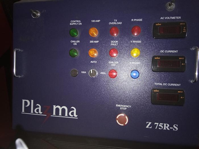
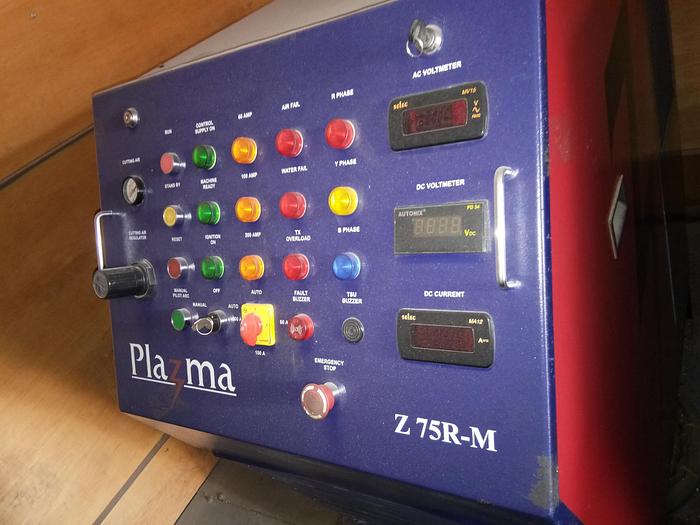
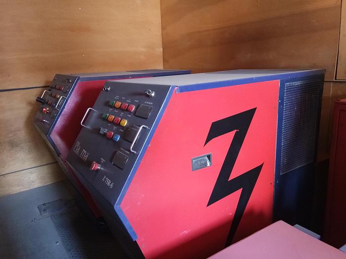
III:2] PLAZMA Power Source:
The US and worldwide patented Plazma torch technology combined with a rugged non-electronic transformer rectifier based power source presents the most reliable metals cutting tool. No effect of dusty and hot atmosphere on Plazma make power source.
At the core a virtually indestructible, compact, water cooled Plazma torch entirely of stainless steel; with just two main consumables, electrode and nozzle, which provide the best cutting economics. A Plazma cut edge is virtually slag free, with minimal heating or distortion. The microstructure shows minimal change ensuring absolutely no post processing problems.
Advantages of Plazma Power Source
Ø Hole Over-burning Technology
Ø Only two consumables which leads to minimum operation cost.
Ø Minimum maintenance cost due to no scaling.
Ø Superior cut quality.
Ø Local Availability of spares.
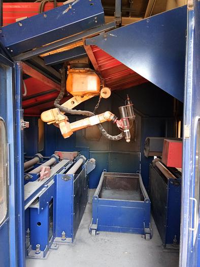
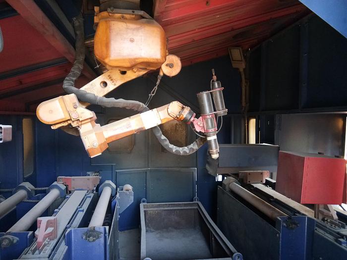
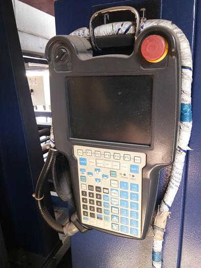
III:3] Fanuc Robot with Controller:
FANUC, Japan make Arc Mate 100iC, 6-axis Robot comes with its controller. Robot arm is mounted on a cantilever in an invert position moving perpendicular to the material to be cut. This set-up gives RoboPlazma™ system distinct advantages over the competition improving reach and flexibility of cutting tool and durability of the system. Maximum dimensions of the structural members capable of being processed in the system are 0.6 m height x 1.2 m width x 20 m length (please note that the dimensions can alter based on the design on the conveyor system and need to be confirmed by Plazma Technologies at the time of order finalization).
• The FANUC Arc Mate 100iC was designed to provide maximum performance and reliability for cutting applications. Automated cutting applications depend on the speed and accuracy of the robot manipulator. The Fanuc 100iC industrial robot design protects the torch cable, reduces wear, and minimizes wire feeder issues.
• The ArcMate 100iC robot creates a large work area and maintains high speeds throughout. These enhancements allow the arm to process large parts without compromising productivity. A slim wrist enables entry into small openings in the work space. Gas lines, air lines, and the wire feeder motor cable are all routed inside the robot arm, resulting in improved reliability and a reduction of setup time.
• The FANUC ArcMate 100iC is compatible with Plasma Cutting equipment and can be interfaced with most types of servo-driven or indexing petitioners.
III.4] 7th Axis Gantry with Columns and Cantilever System:
This is the most unique feature of RoboPlazma™ system that gives flexibility to move the Robot to process multiple 2D and 3D job. Robot is mounted on “Cantilever Arm” which provides large work envelop to the robot. Because of precision 7th axis motion processing of Pipe and large plate is possible with single Robot. Multiple Robots can be mounted on 7th Axis Gantry to multiply process capability.
This moving Cantilever system combined with Roboswift eliminates additional robot for underside processing.
Features:
• Minimal floor space use
• Makes more work space for Robot.
• Vibration Free Motion
• Motion repeatability on Gantry - +/- 0.5 mm in one meter travel length
• Flexibility to scale system as per requirements.
• Improves machine productivity by adding extra robot & its accessories.
III.5] Booster Box Stand, Drag Chain & Cable Tray
For easy and smooth movement of all cables a flexible IGUS drag chain in provided. All cables are routed through drag chain. Drag chain is placed in cable tray to ensure further safety. Length of Drag chain and cable tray varies as per Gantry length.
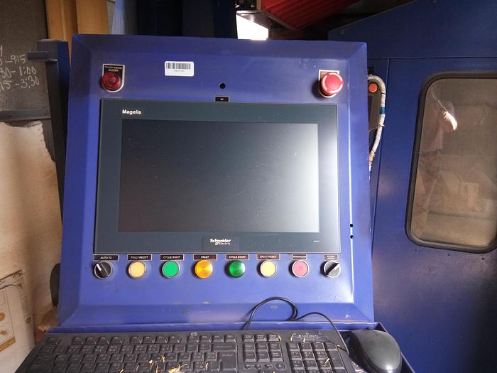
III:6] PDB & PLC Control :
Separate power distribution panel is provided considering total power requirement of RoboPlazma cutting system. Besides Main Power ON/OFF individual control is also provided for safe and easy maintenance and servicing. MCB’s are provided for individual control and safety. Panel is designed and built as per ISI norms.
III:7] MicroBot Laser Sensor Measuring Device:
• Robotically controlled MicroBot laser measuring device sensor fitted on a highly reliable and advanced method for sensing and measuring the material.
• With high precision machined motion elements as base rails, RoboSwift™ programming
enables job capture in the robot’s reference frame and its precise processing.
• This precision measuring MicroBot is synchronized with conveyor to precisely position the job length.
• RoboSwift™ eliminates use of large number of high maintenance mechanical component like grippers, heavy-duty motors, hydraulic & motion elements. This results in high
precision positioning with high reliability and durability.
III.8 ] Material Handling System:
Unique simple designed powered roller conveyors system capable of carrying 12 mtr long structural members of 10 ton (max) are supplied along with RoboPlazma™ beam system.
The roller conveyors are fully integrated with RoboPlazma™ system for auto operation.
Details of In-feed, Out-feed powered roller conveyor, Lift and Carry Cross transfers and hydraulic system as per layout and to suit beam sizes
III.8.1] In-Feed & Out-Feed Roller Conveyors -Standard: 12.5Mtr(L)X 1.0Mtr (W) Each.
These conveyors are required to feed raw beams for RoboPlazma™ Beam system. The in-feed Rollers powered with Motor and Gear box are synchronized with the Robot through VFD. Load bearing capacity is 1020 Kg /mtr.
Heavy duty rollers with two flange type sealed and lubricated bearings with grease cert for additional lubrication and a load capacity of 760 Kg/ each at 100 RPM, double sprocket chain from roller to roller, through CR-shaft 25mm (1”) dia with Eccentric lock. One 7.5 Hp AC drive motor capable of moving weighing max. 10,000 Kg. The 2500mm (100”) section will have two (2) Datum line cam followers. The 100” section will have eight rollers each, of which all are driven. The 1200mm (40”) section will have one (1) Datum line cam follower. The 1200mm ( 40”) sections will have four rollers each, of which all are driven. Included in the price below are the chain covers and connection chains. The Cam followers allow the correct aligning of material to be cut with respect to the machine.
Specifications
| Manufacturer | Fanuc |
| Model | Roboplazma |
| Condition | Used |