1990 LOH TR 4-700 M+A

1990 LOH TR 4-700 M+A
Location:Freiburg im Breisgau, Germany
Available quantity:1
Description
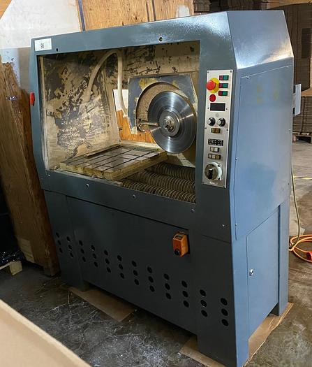
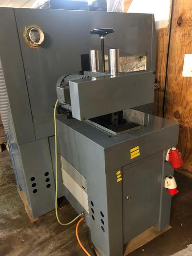
TR 4-700 M+A. Cut-off machine see photos attached.
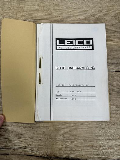
Unfortunately I have no technical documentation, only an instruction manual.
The machine is from the 90's, the exact date is unknown as there is no nameplate.
The machine was running before we put it in storage.
1. stand
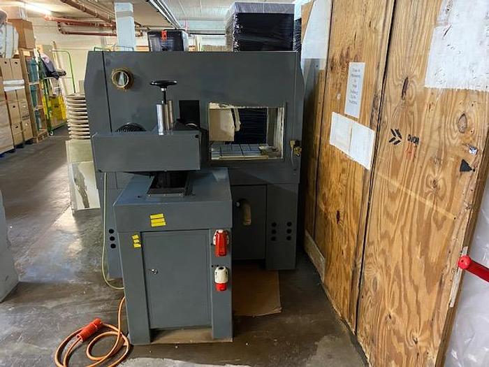
The machine stand is mounted on three vibration-damping rubber support elements. By opening the doors at the side and rear, the interior of the stand can be accessed. stand.
2. crate
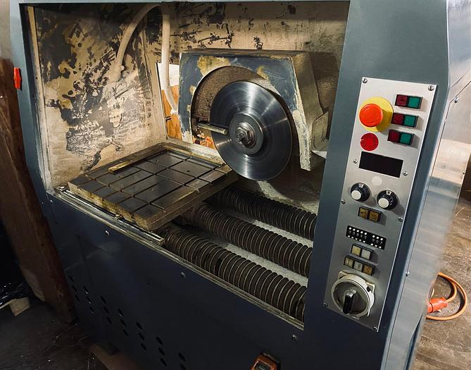
The machine working space is operated from the front. The front
side is equipped with three sliding doors.
A fluorescent tube is mounted on the top of the cover to illuminate the interior.
3. cutting feed unit (version M)
The cutting feed carriage is guided by four ball bushings on two ground precision steel shafts and driven by a hydraulic cylinder.
The maximum cutting feed path 600 mm is limited by the two end positions of the feed cylinder. The round guides and the feed cylinder are covered by bellows inside the wet chamber.
The workpiece fixture is mounted on the cutting feed slide.
is mounted on the cutting feed slide.
3. cut feed unit (version A)
The cut feed carriage is guided by four ball bushings on two ground precision steel shafts.
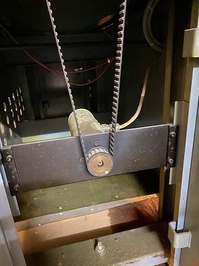
The carriage is driven by a DC servo motor via a ball screw drive. The power is transmitted via a
a toothed belt.
The maximum cutting feed path (600 mm) is limited by contactless limit switches.
by non-contact limit switches. The trip cams can be offset as required within the maximum stroke. The ball screw is protected by a safety coupling. The round guide as well as the drive spindle are covered within the wet area by round bellows.
The workpiece fixture is mounted on the cutting feed slide.
is mounted on the cutting feed slide.
4. cross feed unit (version M)
The cross feed slide is guided by four ball bushings on two ground precision steel shafts. The cross slide is adjusted by hand (at the front of the machine) via a cardan shaft
and a trapezoidal spindle and is max. 200 mm.
On the position indicator the cross feed step size can be read in 0.1 mm.
The vertical unit with grinding spindle is mounted on the cross-feed slide.
4. cross feed unit (version A)
The cross feed slide is guided by four ball bushings on two ground precision steel shafts.
The slide is driven by a stepper motor via a ball screw drive. The power is transmitted
via a toothed belt.
The maximum transverse feed path (200 mm) is limited by contactless limit switches.
The crossfeed increment can be read off in 0.1 mm on the position indicator.
The vertical unit with grinding spindle is mounted on the crossfeed slide.
5. vertical unit
The spindle holder is guided by two vertical columns. The adjusting spindle is driven by a handwheel. It is locked by means of two hexagon nuts (SW 19).
6. grinding spindle and spindle drive
The 120 mm tool spindle is mounted in the spindle holder and is driven by a three-phase motor. The power is transmitted via a toothed belt.
Find more here - https://www.ucymachines.com/
Contact us at - sales@ucymachines.com
Specifications
| Manufacturer | LOH |
| Model | TR 4-700 M+A |
| Year | 1990 |
| Condition | Used |